Rhino is a NURBS modeling program, so ideally every surface created in Rhino should has 4 sides with isocurves running on it. However while making 3D models in Rhino, sometimes I came across with some details that require 5-sided surfaces. Then the question becomes how do you create a 5-sided surface?
I googled a bit by key words "5 sided surface rhino" and here is one comes out on top of search result: http://v5.rhino3d.com/forum/topics/surface-challenge. It is a Q & A thread started by Justin from Australia in Rhino 5 forum.
I share the same reaction with Justin about the quality of patched surface if I use Patch command to create a 5-sided surface. I resonate with his thoughts such as "Network curves doesn't work as there is 5 sides", "Patch doesn't make the edges tangent .. and when you zoom in they are not connecting"
John brock from Robert McNeel & Associates offered his 2 solutions, which I think make sense:
"The first is to extend curves so you can make a 4-sided surface, then Trim away one corner to make the 5th edge. Your model suggests the boundary curve could be the Trimmed edge, suggesting the two surface edges be the edges to extend."
"The second is to create an interior curve that goes from one corner across to another edge. Then you would be modeling two surfaces instead of one to fill the 5-sided hole."
Another method is to buy Autodesk Shape Modeling Plug-In for Rhino. This is a program that allows real-time creating and modifying Class A surfaces. Class-A surfaces are used extensively in exterior design of a car.
And Michael G. provided a file with surfaces modeled in Autodesk Shape Modeling, and I opened it to review. As you can see the image below I cropped from the file, the yellow surfaces in the foreground were created in ASM versus red one created in Solidworks.
I added zebra strips to the 2 group of surfaces and found that the surfaces qualities are very close. I am just wondering if all I need to model in Rhino are generally for products apart from automobiles. Do I need to spend $1,325 to buy the plug-in?
Showing posts with label 3D modeling. Show all posts
Showing posts with label 3D modeling. Show all posts
Wednesday, November 4, 2015

Friday, October 30, 2015
Evaluate Surface Quality
In many cases, the goal of building a surface is to build clean, simple surfaces with good continuity by help of curve and surface analysis tools.
The main reason that some models require more attention to continuity, primarily, is because it will show when manufactured.
The foundation of a quality surface starts with making curves that can create cleaner, simpler surfaces with good continuity. CurvatureGraph, Zebra, and CurvatureAnalysis are the tools we can use to make sure we set things up for the best results.
On this Rhino 5 Level 2 page 131 Exercise 28, the procedure to build quality surface is prescribed in these steps:
Step 1: To evaluate the curves
1 Select the curves in the example file provided by McNeal and start the CurvatureGraph command. The graph tells us that both curves are tangent continuous but have curvature discontinuities in a couple of locations.

The graph tells us that both curves are tangent continuous but have curvature discontinuities in a couple of locations. Assuming we want the surfaces we build from these curves to have curvature continuity throughout, we will be better off modifying these curves before creating the surfaces.
Building a surface that has consistent curvature as a single surface is good modeling practice. The idea is that we need to decide first the surface arrangement, then that will help us understand how to draw clean new curves.
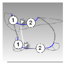
Looking at the bottom curve, we can see two areas that are good candidates for creating the surfaces, so we will start there. There is an area of high curvature at the front (1) and a relatively flat stretch in the
middle with a rapidly increasing curvature at the handle side (2). The top curve is smoother overall, but has similar corresponding regions of curvature. By examining the current curves, we can identify two curves to build at the top and bottom. The white vertical curve intersects the top and bottom curves at the curvature discontinuity of the top curve, which is a modified circle, and on an abrupt change in curvature on the lower curve. This intersection is where we will start and end our modified curves.
Step 2: To build the modified curves

1 Using the current curves as a reference, draw four new curves of degree five with six points. The goal is to redraw the top and bottom curves in two parts each. Keep in mind what you know about continuity,
CurvatureGraph, tangent directions, and EndBulge. Try to keep the control point locations even and progressive.

2 Analyze your curves with the CurvatureGraph command. Try to get the graph clean with minimal, abrupt changes, while at the same time match the original curve shapes as closely as possible. They cannot be exactly the same as the originals if they are to have better continuity, but it should be possible to get close.
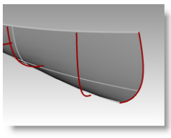
Step 3: To make the surfaces for the bottle from edge curves There are four, single-span, curves that define each area for the surfaces. In this part of the exercise we will use the EdgeSrf command (Surface menu: Edge curves) to create the surfaces. This command is one that uses the input curve structure to create the surface. It works best if the curves on opposite sides of the rectangle match each other. The
resulting surface will be simpler. Since we have taken care to meet this criterion, all of the vertical curves are degree 3 with four points, and the curves we just made are degree five with six points, the resulting surfaces will share this structure.

1 Select four curves that define one of the surfaces.
2 Start the EdgeSrf command (Surface menu: Edge curves).
3 Repeat steps 1 and 2 for the other surface.
4 Check the surfaces with the Zebra command.

The zebra stripes have a nice even flow but the surfaces are clearly not tangent at the vertical edge

1 Use the MatchSrf command (Surface menu: Surface Edit Tools > Match) to match the surfaces for Curvature. Try matching in both directions, and with or without Average surfaces set.
2 Check the surfaces with the Zebra command.
The zebra stripes have a nice even flow with no discontinuity at the common edge.
The main reason that some models require more attention to continuity, primarily, is because it will show when manufactured.
The foundation of a quality surface starts with making curves that can create cleaner, simpler surfaces with good continuity. CurvatureGraph, Zebra, and CurvatureAnalysis are the tools we can use to make sure we set things up for the best results.
On this Rhino 5 Level 2 page 131 Exercise 28, the procedure to build quality surface is prescribed in these steps:
Step 1: To evaluate the curves
1 Select the curves in the example file provided by McNeal and start the CurvatureGraph command. The graph tells us that both curves are tangent continuous but have curvature discontinuities in a couple of locations.
The graph tells us that both curves are tangent continuous but have curvature discontinuities in a couple of locations. Assuming we want the surfaces we build from these curves to have curvature continuity throughout, we will be better off modifying these curves before creating the surfaces.
Building a surface that has consistent curvature as a single surface is good modeling practice. The idea is that we need to decide first the surface arrangement, then that will help us understand how to draw clean new curves.
Looking at the bottom curve, we can see two areas that are good candidates for creating the surfaces, so we will start there. There is an area of high curvature at the front (1) and a relatively flat stretch in the
middle with a rapidly increasing curvature at the handle side (2). The top curve is smoother overall, but has similar corresponding regions of curvature. By examining the current curves, we can identify two curves to build at the top and bottom. The white vertical curve intersects the top and bottom curves at the curvature discontinuity of the top curve, which is a modified circle, and on an abrupt change in curvature on the lower curve. This intersection is where we will start and end our modified curves.
Step 2: To build the modified curves

1 Using the current curves as a reference, draw four new curves of degree five with six points. The goal is to redraw the top and bottom curves in two parts each. Keep in mind what you know about continuity,
CurvatureGraph, tangent directions, and EndBulge. Try to keep the control point locations even and progressive.
2 Analyze your curves with the CurvatureGraph command. Try to get the graph clean with minimal, abrupt changes, while at the same time match the original curve shapes as closely as possible. They cannot be exactly the same as the originals if they are to have better continuity, but it should be possible to get close.
Step 3: To make the surfaces for the bottle from edge curves There are four, single-span, curves that define each area for the surfaces. In this part of the exercise we will use the EdgeSrf command (Surface menu: Edge curves) to create the surfaces. This command is one that uses the input curve structure to create the surface. It works best if the curves on opposite sides of the rectangle match each other. The
resulting surface will be simpler. Since we have taken care to meet this criterion, all of the vertical curves are degree 3 with four points, and the curves we just made are degree five with six points, the resulting surfaces will share this structure.

1 Select four curves that define one of the surfaces.
2 Start the EdgeSrf command (Surface menu: Edge curves).
3 Repeat steps 1 and 2 for the other surface.
4 Check the surfaces with the Zebra command.

The zebra stripes have a nice even flow but the surfaces are clearly not tangent at the vertical edge
Step 4: To match the surfaces for the bottle with MatchSrf
1 Use the MatchSrf command (Surface menu: Surface Edit Tools > Match) to match the surfaces for Curvature. Try matching in both directions, and with or without Average surfaces set.
2 Check the surfaces with the Zebra command.
The zebra stripes have a nice even flow with no discontinuity at the common edge.
Conclusion
Although in the training manual it does not state clearly how to make Step 2-1. work , the way to make it work is draw four new curves of degree five with six points.
MatchSrf is a useful command in blending two surface with continuity.
Matching the larger surface to the smaller one, without Average, results in a more erratic control point arrangement on the larger surface than any other combination, particularly the second row from the top.
Other considerations being equal, the best choice is the surface with the most regular, even control point arrangement.
Other considerations being equal, the best choice is the surface with the most regular, even control point arrangement.
Friday, June 5, 2015
Rhino 3D: Anything you can do I can do better!
As generally believed, there are some fine details that set
Rhino apart from parametric CAD. In one aspect, Rhino can create a surface that
exists mathematically, while the surface is hard to be made by an apparent set
of rules in parametric modeling. Parametric CAD programs have more stringent
conditions on creating a surface. If the conditions are satisfied, then the
surface can be generated. If not, the surface will fail. One of the reasons for
that I figure is because parametric CAD is designed for engineering and in some
cases scientific applications. The 3D models or surfaces in parametric CAD must
be precise and anchored on measureable parametric data. However in Rhino, it
provides you with multiple ways to create a surface that is hard to defined in
mathematical terms even though the surface exists mathematically.
Look at this example of Lofted surfaces from Rhino 5 Level 1 training manual, Exercise 59— Canoe. (The manual is here)When you prepare sketch profiles (curves) to make a lofted surface in Solidworks, the program will have to make sure the newly lofted surface go through every sketch profile (curves) with smooth curvilinear transition. It is rigidly constructed and conformed to the sketch profiles. Whereas in Rhino, you can have some other options:

Above are the finished Canoe and its original sketch profiles (curves)

In the Loft Options dialog box, the default of Style is Normal. A surface is fitted over the curves just it can be done in Solidworks.

Look at this example of Lofted surfaces from Rhino 5 Level 1 training manual, Exercise 59— Canoe. (The manual is here)When you prepare sketch profiles (curves) to make a lofted surface in Solidworks, the program will have to make sure the newly lofted surface go through every sketch profile (curves) with smooth curvilinear transition. It is rigidly constructed and conformed to the sketch profiles. Whereas in Rhino, you can have some other options:

In the Loft Options dialog box, the default of Style is Normal. A surface is fitted over the curves just it can be done in Solidworks.
Or, in the Loft Options dialog box, you can switch Style to
Straight sections, A surface is fitted through the curves, but the sections are
straight between the curves. It is much like a poly model.
Or, in the Loft Options dialog box, switch Style to Loose, a
surface is created that uses the same control points as the curves. The surface
follows the curves more loosely. Use this option when you want the surface to
conform to the control points of the input curves.
This is an example that illustrates one of the
advantages a CAD user can see in Rhino over CAD programs like Solidworks – its
versatility and flexibility in getting surface made.
Wednesday, June 3, 2015
Quest for the strength of Rhino 3D
I have came to know of Rhino 3D for more than 10 years. In the
beginning, when it was still in its infancy, I downloaded the free trial
version to play for a while. At the first sight of Rhino 3D, I was quite amazed
because I thought how a NURBS modeling program can be so affordable. Back then
I used Alias Studio at work to create some complex curvilinear shapes that were
then hard to be modelled by Solidworks I used every day. Honestly I was a bit distasteful
of Alias Studio. It was a program built on Silicon Graphics workstation and was
very hard to use because it was so powerful and has so many variables that need
my attention and tweaking. I was lost often in using Alias and thus quipped that learning to
use Alias is like studying rocket science.
Then Rhino 3D came. It was offered as a low-cost but
powerful enough NURBS modeling program under a unique business model of Robert
McNeel & Associates. Though I downloaded the program to try but never paid
a full attention to learn it. My company even sent me to learn it at Magnetic
Visions in Brooklyn, NY in 2011. Through the training I learned the basic
modeling skills in Rhino 3D, but thought that why bothering with Rhino while in
Solidworks I can use hybrid of solid/surface modeling techniques to take care
of most 3D modeling task.
I decided lately to dig deeper into learning Rhino and encountered several issues, which I have to get used to. The issues I have with Rhino 3D are: first of all, it is a
program born out of AutoCAD era, meaning its interface bears the resemblance of
CAD programs in that era. It has a command prompt window. Even though there is
an alternative icon in pulldown menu to get to each command, a user still has
to use command lines to get to the options under a command most of the time.
Some commands are followed by the dialogue windows once selected, but only a few.
Secondly, to make a sketch for modeling, the sketch normally falls on front, side,
top or construction plane. This is something I have been struggling with
because I am so used to parametric modeling in Solidworks where I can simply
click on a plane surface to start a sketch. So far as I know, in Rhino to start a sketch it is easier to adhere the sketch to front, side, top or construction plane. Elevator
Mode may be the only antidote I have found so far to break a 2D sketch away from the
construction plane to which it adhere. Thirdly, Solidworks
has simplified the steps of many model features that employ Boolean algorithm,
for example, shelling a solid block. Shell command only becomes available since Rhino 5. Fourthly and the least is that Rhino is
not a CAD program for engineers, it lacks the parametric modeling features and
does not have a design feature tree that can be rolled back and forth as in Solidworks.
So that I have to bear in mind that certain modeling tasks can be done better elsewhere than in Rhino. I just have to find the strength of Rhino where other CAD programs fall short or cannot do better. Keep reading ....
So that I have to bear in mind that certain modeling tasks can be done better elsewhere than in Rhino. I just have to find the strength of Rhino where other CAD programs fall short or cannot do better. Keep reading ....
Tuesday, June 2, 2015
Rhino 3D: 4-sided surfaces
In Exercise 57 page 162 - Creating simple surfaces, 6 ways to make a 4-sided surface are demonstrated:

From the Surface menu click Plane, and then click Corner to Corner.

From the Surface menu click Plane, and then click Vertical.

From the Surface menu click Plane, and then click 3 Points.
Beware that, in this method, SmartTrack is used to track a point from the top of the vertical plane for height of the place. When doing this, I need to turn on Object Snap (with End and Point checked) on status bar and drag the cursor to lightly touch the top corner of the vertical plane I just made in Step 2. Drag the tracking point until the surface is tilted slightly and click.

4. To create a plane from corner points:
From the Surface menu click Corner Points.
When picking the points in the next four steps, I must pick them in a clockwise direction. I tried this command and found that I can make not only 4- but 3-sided plane with this command.

Turn Planar mode on in status bar. Draw a curve that starts and ends at the top of the two vertical surfaces as shown below. Planar mode keeps this curve on the same plane as the surface corners.
From the Surface menu click Planar Curves.

From the Surface menu click Edge Curves.
This is an excellent exercise that guides me through 5 more unique ways to make 4-sided surface except the simplest rectangle plane surface. But these surfaces are still independent from one another except ever 2 surfaces share one of the 12 edges in the model. I still can move a surface by click and drag it.
I will have to use Join command to stitch them together like this:

Wednesday, May 27, 2015
T-Splines in Rhino: preparing NURBS surfaces in Rhino for T-Splines
When preparing T-Splines optimal surfaces in Rhino, I use Rebuild command to have enough control points on the surfaces. In this tutorial (https://youtu.be/JZ_bA_4XTpg), it teaches me how to prepare Rhino's NURBS surfaces to be used in T-Splines.
Plan surfaces in Rhino are all degree 3. It means the minimum point count in the U or V direction is 4. When the surface with 4 points in U or V direction is converted in T-Splines, I will get one single face. But if I increase the point count to 5 in U or V direction, I will get 2 in both directions or 4 faces total.
So it is easier for me to think in terms of how many faces are in my model when I convert them into T-Splines. If I want X faces in U or V direction in my T-Splines model, then I rebuild my NURBS surface to X plus 3 control points in that direction.
Thursday, May 14, 2015
OnShape - the promise of CAD in the future is here now
I signed up a free account at OnShape and tried it today. I would say it is a promising CAD solution that could shape the future of CAD. By using OnShape, a user can experience what the things will come in CAD industry.
OnShape is a CAD system built on the cloud. Your internet
browser is turned into a platform on which the CAD programs like OnShape can
run. Whereas OnShape is more than a CAD program and that is why I call it a
system. It comprises not just the CAD program, but the online collaboration
tool, online data storage, and mobile app. Literally it is a Software as a
Service system.
For starters: If you are not familiar with SaaS concept, you
can look at the example of salesforce.com as the harbinger of SaaS, or
later Adobe’s Creative Cloud. The software is built on an online platform and
is subscription-based without upfront purchase of the entire software. So a user
of the software does not own a copy of the software and only pay the
subscription.
As in the case of OnShape and other SaaS programs, the
programs are constantly updated without version installation and/or upgrades.
That is why OnShape is what the CAD programs look like in the future.
The 2 most distinctive features to me in OnShape are the
direct editing function and online realtime collaboration. Given OnShape is a feature-based
parametric modeling program, it allows a user to break the ranks of feature
tree to directly alter the parameters on a feature and to determine the scope
of propagating changes after the alteration. As far as online collaboration,
OnShape’s development team claims that multiple users can work on different
portions of the same part or assembly simultaneously.
The modeling tool in OnShape at this moment is heavily
depending on 2D sketches and solid modeling. As an industrial designer, I would
expect that more Spline curve and NURBS surfacing modeling tools will be added
later to strengthen form creation capability inside OnShape. Or even further, it
will be ideal that the subdivision modeling be also available in the future.
I have not tried out every major feature in OnShape but if
all claims made by its developers are true, OnShpe will be an amazing and
ground breaking development in CAD industry.Friday, May 1, 2015
Rhino: Difference between _Curve and _InterpCrv
The InterpCrv command draws a curve through selected locations in space. It is called the interpolated curve in Rhino as it is called spline in many CAD programs.
(http://docs.mcneel.com/rhino/5/help/en-us/commands/interpcrv.htm)
The Curve command draws a curve from control points.
Usually I would use InterpCrv to create spline curve because this is the same method I use often in Solidworks to create spline curve.
(http://docs.mcneel.com/rhino/5/help/en-us/commands/interpcrv.htm)
The Curve command draws a curve from control points.
Usually I would use InterpCrv to create spline curve because this is the same method I use often in Solidworks to create spline curve.
Thursday, April 30, 2015
Rhino 3D: Insert Knot comand under Control Points
Part of the information needed to define a NURBS curve is a list of numbers called a knot vector and the values of the numbers in this list are called knots.(http://docs.mcneel.com/rhino/5/help/en-us/commands/insertknot.htm)
Insert Knot command allows me to add knots on curves or surfaces. If a knot is added to a surface, an isoparametric curve (a curve of constant u- or v-value on a surface) will display on that surface. Then I will have to use Toggle option under InsertKnot to determine the direction of the curve between u and v.
Insert Knot command allows me to add knots on curves or surfaces. If a knot is added to a surface, an isoparametric curve (a curve of constant u- or v-value on a surface) will display on that surface. Then I will have to use Toggle option under InsertKnot to determine the direction of the curve between u and v.
Rhino 3D - Rebuild command
In Rhino 3D, Rebuild under Edit menu is pretty powerful tool to subdivide a surface. Don't forget!
By McNeel Associates, the developer of Rhino, the Rebuild command "reconstructs selected curves or surfaces to a specified degree and control point number."(http://docs.mcneel.com/rhino/5/help/en-us/commands/rebuild.htm)
By McNeel Associates, the developer of Rhino, the Rebuild command "reconstructs selected curves or surfaces to a specified degree and control point number."(http://docs.mcneel.com/rhino/5/help/en-us/commands/rebuild.htm)
Subscribe to:
Posts (Atom)