Wednesday, November 25, 2015

Rendering a Clear Insert in a Clear Caddy

Lately I have a chance to work on a rendering like this carrying caddy for a skincare gift set shown below and I have learned some tricks in rendering. I would like to record the tricks here for future reference.

 
I used Photoview 360 in Solidworks 2014 to make this rendering image. As seen in the image, there are 3 products in the caddy, 2 skincare bottles and 1 spray mist, which are held by a clear vacuum-formed insert on the bottom of the caddy.

The most challenging part of the rendering task is to render the clear vacuum-formed insert through the tinted pink caddy. As I thought in the beginning that the light from different light sources in the scene - ambient light, directional lights, environmental light - will travel through the caddy and the vacuum-formed insert to make the insert looks clear. However, it turns out the caddy stays tinted pink but the insert appears to be dark gray. I eventually achieved the effect as shown in the above image by tweaking Photoview 360's material settings after several attempts. Here are some settings I used that work:

I. For the caddy's illumination under Appearances tab:

1. I chose clear polycarbonate as the material for both caddy and the clear insert. I originally chose glass for the caddy, and it did not work.
2. The index of refraction is 0.90. Set to 1.0 will simulate light travel through vacuum, and it did not work in my case. The setting above 1.0 will also make the insert very dark.
3. The transparent amount of the caddy is 0.80

II. For the vacuum formed insert's illumination under Appearances tab, I need to make the insert an luminous object, so it can emit light through the tinted pink caddy. Rather than relying on the reflective light that may bounce off the white skincare bottle through the insert and caddy to let a viewer like you and me to perceive the insert as a clear object, I have to add the illumination to the insert. The reason at doing this is that once the light travels from outside through the caddy, it is weakened and hardly can bounce back out of the caddy. So I must reinforce the intensity of the light around the insert by adding illumination to the insert. Here are my setting for the vacuum-formed insert:

1. I still used clear polycarbonate as the material
2. Luminous intensity is increased from 0 to 0.080 w/srm^2
3. The index of refraction increased from 1.0 to 1.33. 1.33 is approximately the distortion caused by light traveling through water, assuming the surfaces have some transparency.
4. Transparent amount is set to 1.00, which is equal to completely transparent.

In the above image, it shows how transparent the vacuum-formed insert becomes through the tinted pink caddy.


Wednesday, November 4, 2015

5-sided Surface challenge in Rhino 3D

Rhino is a NURBS modeling program, so ideally every surface created in Rhino should has 4 sides with isocurves running on it. However while making 3D models in Rhino, sometimes I came across with some details that require 5-sided surfaces. Then the question becomes how do you create a 5-sided surface?

I googled a bit by key words "5 sided surface rhino" and here is one comes out on top of search result: http://v5.rhino3d.com/forum/topics/surface-challenge. It is a Q & A thread started by Justin from Australia in Rhino 5 forum.

I share the same reaction with Justin about the quality of patched surface if I use Patch command to create a 5-sided surface. I resonate with his thoughts such as "Network curves doesn't work as there is 5 sides", "Patch doesn't make the edges tangent .. and when you zoom in they are not connecting"

John brock from Robert McNeel & Associates offered his 2 solutions, which I think make sense:

"The first is to extend curves so you can make a 4-sided surface, then Trim away one corner to make the 5th edge. Your model suggests the boundary curve could be the Trimmed edge, suggesting the two surface edges be the edges to extend."

"The second is to create an interior curve that goes from one corner across to another edge. Then you would be modeling two surfaces instead of one to fill the 5-sided hole."

Another method is to buy Autodesk Shape Modeling Plug-In for Rhino. This is a program that allows real-time creating and modifying Class A surfaces. Class-A surfaces are used extensively in exterior design of a car.

And Michael G. provided a file with surfaces modeled in Autodesk Shape Modeling, and I opened it to review. As you can see the image below I cropped from the file, the yellow surfaces in the foreground were created in ASM versus red one created in Solidworks.

I added zebra strips to the 2 group of surfaces and found that the surfaces qualities are very close. I am just wondering if all I need to model in Rhino are generally for products apart from automobiles. Do I need to spend $1,325 to buy the plug-in?


Friday, October 30, 2015

Evaluate Surface Quality

In many cases, the goal of building a surface is to build clean, simple surfaces with good continuity by help of curve and surface analysis tools.
The main reason that some models require more attention to continuity, primarily,  is because it will show when manufactured.
The foundation of a quality surface starts with making curves that can create cleaner, simpler surfaces with good continuity. CurvatureGraph, Zebra, and CurvatureAnalysis are the tools we can use to make sure we set things up for the best results.

On this Rhino 5 Level 2 page 131 Exercise 28, the procedure to build quality surface is prescribed in these steps:


Step 1: To evaluate the curves

1 Select the curves in the example file provided by McNeal and start the CurvatureGraph command. The graph tells us that both curves are tangent continuous but have curvature discontinuities in a couple of locations.


The graph tells us that both curves are tangent continuous but have curvature discontinuities in a couple of locations. Assuming we want the surfaces we build from these curves to have curvature continuity throughout, we will be better off modifying these curves before creating the surfaces.


Building a surface that has consistent curvature as a single surface is good modeling practice. The idea is that we need to decide first the surface arrangement, then that will help us understand how to draw clean new curves.

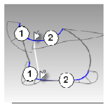
Looking at the bottom curve, we can see two areas that are good candidates for creating the surfaces, so we will start there. There is an area of high curvature at the front (1) and a relatively flat stretch in the
middle with a rapidly increasing curvature at the handle side (2). The top curve is smoother overall, but has similar corresponding regions of curvature. By examining the current curves, we can identify two curves to build at the top and bottom. The white vertical curve intersects the top and bottom curves at the curvature discontinuity of the top curve, which is a modified circle, and on an abrupt change in curvature on the lower curve. This intersection is where we will start and end our modified curves.


Step 2: To build the modified curves


1 Using the current curves as a reference, draw four new curves of degree five with six points. The goal is to redraw the top and bottom curves in two parts each. Keep in mind what you know about continuity,
CurvatureGraph, tangent directions, and EndBulge. Try to keep the control point locations even and progressive.


2 Analyze your curves with the CurvatureGraph command. Try to get the graph clean with minimal, abrupt changes, while at the same time match the original curve shapes as closely as possible. They cannot be exactly the same as the originals if they are to have better continuity, but it should be possible to get close.

Step 3: To make the surfaces for the bottle from edge curves There are four, single-span, curves that define each area for the surfaces. In this part of the exercise we will use the EdgeSrf command (Surface menu: Edge curves) to create the surfaces. This command is one that uses the input curve structure to create the surface. It works best if the curves on opposite sides of the rectangle match each other. The
resulting surface will be simpler. Since we have taken care to meet this criterion, all of the vertical curves are degree 3 with four points, and the curves we just made are degree five with six points, the resulting surfaces will share this structure.


1 Select four curves that define one of the surfaces.
2 Start the EdgeSrf command (Surface menu: Edge curves).
3 Repeat steps 1 and 2 for the other surface.
4 Check the surfaces with the Zebra command.


The zebra stripes have a nice even flow but the surfaces are clearly not tangent at the vertical edge


Step 4: To match the surfaces for the bottle with MatchSrf

1 Use the MatchSrf command (Surface menu: Surface Edit Tools > Match) to match the surfaces for Curvature. Try matching in both directions, and with or without Average surfaces set.

2 Check the surfaces with the Zebra command.
The zebra stripes have a nice even flow with no discontinuity at the common edge.

 
Conclusion
 
Although in the training manual it does not state clearly how to make Step 2-1. work , the way to make it work is draw four new curves of degree five with six points.
 
MatchSrf is a useful command in blending two surface with continuity.
 
Matching the larger surface to the smaller one, without Average, results in a more erratic control point arrangement on the larger surface than any other combination, particularly the second row from the top.

Other considerations being equal, the best choice is the surface with the most regular, even control point arrangement.


Wednesday, October 28, 2015

Rebuilding Curves

I found it crucial to have curves rebuilt before creating a new surface from them. One aim I know of for rebuilding a curve is to make the curve into a single span curve. As stated in Rhino 5's training manual level 2, although it is not necessary to get high quality surfaces by doing this, it produces predictable results.

In this example found on page 99 of the level 2 training manual, first on each endpoint of a curve, a tangent line is drawn by using Line command with Extension option. Each of the 2 lines maintains the tangency direction of an original curve from each end point and coming back towards the curve.


Then use the Rebuild command (Edit menu: Rebuild) to rebuild the curve. In the Rebuild Curve dialog, change the Degree to 5 and the Point Count to 6 points. Uncheck Delete input, check Create new object on current layer. It is better practice that the original curves are kept in a separate layer. Click the Preview button. Note how much the curves deviate from the originals.
Although there is a Rebuild option in many commands such as Loft, rebuilding the curves before lofting them gives you control over the degree of the curves as well as the number of control points.

Lock the Original Curves (in a separate layer if you can). We need to see these curves but we do not want to be able to select them. Select one of the rebuilt curves, and turn on the Control points and Curvature graph.

Fair the curve by adjusting points until it matches the original curve closely enough. Start by moving the second control point from each end of the rebuilt curve onto the tangent line. Use the Near object snap to drag along the tangent line.


Check the curvature graph to make sure the curve has smooth transitions. The curves are fair when the points are adjusted so the rebuilt curves match the original locked curves closely, with good graphs.

Rhino 3D Modeling Process

Rhino 3D is different from parametric 3D CAD programs in the respect that there is no design feature tree. Since Rhino 3D is not feature-based, the line(s) or curve(s) for a surface are independent from the surface by default.

With that being said, however, there are different methods to preserve the building history of a 3D model. And certain parent/child relationships can be established and maintained when the design is updated. I can either 1) turn on Record History or  2) manage to separate curves/lines and the surfaces created from them into different layers.

 For method 1) turn on Record History:
Based on Rhino's help menu: the History command "Stores the connection between a command's input geometry and the result so that when the input geometry changes, the result updates accordingly. For example, with History recording and Update turned on, a lofted surface can be changed by editing the input curves."

When using method 2) with layers to manage the parent/child relationships, I will assign lines/curves to one layer and create a new layer. Then the new layer will be set as the current layer from which the new surfaces will be created. Next time when I need to update the sketch profiles in lines/curves, new surfaces will be generated from the updated lines/curves without interfering with existing surfaces.

As direct editing function is a natural way to create, edit and generate 3D models in Rhino 3D, it will require more efforts from me to get familiar with the 2 above-mentioned methods in maintaining parent/child relationship.

Friday, September 18, 2015

Curve fairing to control surface quality

Going through Rhino 5 Level 2 training manual, I often learn details in 3D modeling of which I was not aware.....

There is an exercise titled "Curve fairing to control surface quality" in the manual,
 it teaches me that many curves in Rhino coming from many sources need to be optimized for quality. It mentions curve fairing as a technique used in Rhino to optimize a curve for 3D modeling. It defines fairing as "a technique used to simplify curves while improving their curvature graphs and keeping their shape
within tolerance." It also states: "it is especially important to fair curves that are generated from digitized data, intersections, extracted isocurves, or curves from two views."

It explains that single-span curves work better for this fairing process. What is a single span curve? A single span curve is a curve that has one more control point than the degree. For examples a degree 3 curve with 4 control points, and so on.


To fair a curve, it starts with rebuilding a curve. This is when Rebuild command is used. In the dialog window of Rebuild, the number of control points and the degree of curve can be updated. As a single-span curve works best in curve fairing, so it is seen in the following image that in the Rebuild Curve dialog, change the Degree to 5 and the Point Count to 6 points. Uncheck Delete input, check Create new object on current layer.
 
This makes the curves into single-span curves. Single-span curves are Bézier curves. A single-span curve is a curve that has degree +1 control points. While this is not necessary to get high quality surfaces, it produces predictable results. I can also combine Divide command with PointDeviation to detect the deviation of the points on a curve and to adjust the points' positions until the points are located within the range of good deviation and are identified in blue as "good points".


The end result of a new surface from these curves after fairing will be that the shape and quality of the surface has very few isocurves but it is very close to the shape of the first surface. 

I can then analyze the surface with CurvatureAnalysis. It will shows the smooth transitions in the false color display, indicating smooth curvature transitions in the surface.


Friday, August 7, 2015

Process Lab in Cooper Hewitt Design Museum


Anyone who is interested in product design should pay a visit to Cooper Hewitt National Design Museum if he or she happens to be in New York City. The visit will be a one-of-the-kind experience for a design aficionado. The museum just reopened its door this year after renovation. Even though the museum is still located in the existing historic Carnegie Mansion by Central Park, it is aimed at providing immersive experience for its visitors through the physical exhibition display and interactive media. It offers each visitor who pays admission at the counter a high-tech wand so-called “the Pen” by the museum to collect his/her images from the exhibitions, interactive tables or his/her own creation on the tables. The Pen helps storing up the visitor’s collection onto Cooper Hewitt’s website from which the visitor can retrieve the collection on his/her own devices after the visit. Designers at Cooper Hewitt in charge of this unique user experience design shared an very interesting coverage on how they develop and design the user experience.
However, for designers, the most impressive part of the new museum is the process lab. In this newly created Process Lab, Cooper Hewitt has drawn on its extensive experience through the years in planning and providing education programs on design for people of all ages to create an immersive learning space that brings the design process to life. The museum asks a visitor to “play designers” in this lab to gain the first hand experience on how things are created and made through the design process. Isn't it that we used to do role playing in our childhood play time? So play designers will enable the visitors to immerse in the design experience. Guided by the display panels in the lab showing assorted design processes, methods, and approaches, visitors can try their hands on designing objects. These guiding principles on the panels to me are reminiscences of methods and skills I have acquired in the design school, such as:

·       Brainstorming
·       Think of the human scale when designing: as on one corner of the wall showing Henry Dreyfuss Associates’ male and female figures from its groundbreaking book, the Measure of Man and Woman
·       Mix and match to improvise an interesting combination (or an impromptu0
·       To draw and to make prototype

In problem solving section of the lab, IDEO showcases its renown design process and its real-world case study. And once again IDEO proves itself to be the world class innovation consultant firm.
The lab even shows a latest 3D printer at work and its output samples. The 3D printers combining with Computer-Aided-Design programs are creating new realm of design that has never been envisioned before. As it is evident in the generative design  samples in this lab that are part of bio-mimicry and part of pattern morphology.

The lab very much leans toward introducing visitors to design process used by industrial designers, mechanical engineers, and human factor specialists with very light coverage on the graphic, interior or architectural design. But for novices to design process, going through the tasks offered in this lab definitely will make their experience with design very engaging and immersive. And for designers, this is the place to rekindle with skills and knowledge we should implement daily in our projects.