Rhino is a NURBS modeling program, so ideally every surface created in Rhino should has 4 sides with isocurves running on it. However while making 3D models in Rhino, sometimes I came across with some details that require 5-sided surfaces. Then the question becomes how do you create a 5-sided surface?
I googled a bit by key words "5 sided surface rhino" and here is one comes out on top of search result: http://v5.rhino3d.com/forum/topics/surface-challenge. It is a Q & A thread started by Justin from Australia in Rhino 5 forum.
I share the same reaction with Justin about the quality of patched surface if I use Patch command to create a 5-sided surface. I resonate with his thoughts such as "Network curves doesn't work as there is 5 sides", "Patch doesn't make the edges tangent .. and when you zoom in they are not connecting"
John brock from Robert McNeel & Associates offered his 2 solutions, which I think make sense:
"The first is to extend curves so you can make a 4-sided surface, then Trim away one corner to make the 5th edge. Your model suggests the boundary curve could be the Trimmed edge, suggesting the two surface edges be the edges to extend."
"The second is to create an interior curve that goes from one corner across to another edge. Then you would be modeling two surfaces instead of one to fill the 5-sided hole."
Another method is to buy Autodesk Shape Modeling Plug-In for Rhino. This is a program that allows real-time creating and modifying Class A surfaces. Class-A surfaces are used extensively in exterior design of a car.
And Michael G. provided a file with surfaces modeled in Autodesk Shape Modeling, and I opened it to review. As you can see the image below I cropped from the file, the yellow surfaces in the foreground were created in ASM versus red one created in Solidworks.
I added zebra strips to the 2 group of surfaces and found that the surfaces qualities are very close. I am just wondering if all I need to model in Rhino are generally for products apart from automobiles. Do I need to spend $1,325 to buy the plug-in?
Showing posts with label CAD. Show all posts
Showing posts with label CAD. Show all posts
Wednesday, November 4, 2015


Friday, October 30, 2015
Evaluate Surface Quality
In many cases, the goal of building a surface is to build clean, simple surfaces with good continuity by help of curve and surface analysis tools.
The main reason that some models require more attention to continuity, primarily, is because it will show when manufactured.
The foundation of a quality surface starts with making curves that can create cleaner, simpler surfaces with good continuity. CurvatureGraph, Zebra, and CurvatureAnalysis are the tools we can use to make sure we set things up for the best results.
On this Rhino 5 Level 2 page 131 Exercise 28, the procedure to build quality surface is prescribed in these steps:
Step 1: To evaluate the curves
1 Select the curves in the example file provided by McNeal and start the CurvatureGraph command. The graph tells us that both curves are tangent continuous but have curvature discontinuities in a couple of locations.

The graph tells us that both curves are tangent continuous but have curvature discontinuities in a couple of locations. Assuming we want the surfaces we build from these curves to have curvature continuity throughout, we will be better off modifying these curves before creating the surfaces.
Building a surface that has consistent curvature as a single surface is good modeling practice. The idea is that we need to decide first the surface arrangement, then that will help us understand how to draw clean new curves.
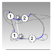
Looking at the bottom curve, we can see two areas that are good candidates for creating the surfaces, so we will start there. There is an area of high curvature at the front (1) and a relatively flat stretch in the
middle with a rapidly increasing curvature at the handle side (2). The top curve is smoother overall, but has similar corresponding regions of curvature. By examining the current curves, we can identify two curves to build at the top and bottom. The white vertical curve intersects the top and bottom curves at the curvature discontinuity of the top curve, which is a modified circle, and on an abrupt change in curvature on the lower curve. This intersection is where we will start and end our modified curves.
Step 2: To build the modified curves

1 Using the current curves as a reference, draw four new curves of degree five with six points. The goal is to redraw the top and bottom curves in two parts each. Keep in mind what you know about continuity,
CurvatureGraph, tangent directions, and EndBulge. Try to keep the control point locations even and progressive.

2 Analyze your curves with the CurvatureGraph command. Try to get the graph clean with minimal, abrupt changes, while at the same time match the original curve shapes as closely as possible. They cannot be exactly the same as the originals if they are to have better continuity, but it should be possible to get close.
Step 3: To make the surfaces for the bottle from edge curves There are four, single-span, curves that define each area for the surfaces. In this part of the exercise we will use the EdgeSrf command (Surface menu: Edge curves) to create the surfaces. This command is one that uses the input curve structure to create the surface. It works best if the curves on opposite sides of the rectangle match each other. The
resulting surface will be simpler. Since we have taken care to meet this criterion, all of the vertical curves are degree 3 with four points, and the curves we just made are degree five with six points, the resulting surfaces will share this structure.

1 Select four curves that define one of the surfaces.
2 Start the EdgeSrf command (Surface menu: Edge curves).
3 Repeat steps 1 and 2 for the other surface.
4 Check the surfaces with the Zebra command.

The zebra stripes have a nice even flow but the surfaces are clearly not tangent at the vertical edge

1 Use the MatchSrf command (Surface menu: Surface Edit Tools > Match) to match the surfaces for Curvature. Try matching in both directions, and with or without Average surfaces set.
2 Check the surfaces with the Zebra command.
The zebra stripes have a nice even flow with no discontinuity at the common edge.
The main reason that some models require more attention to continuity, primarily, is because it will show when manufactured.
The foundation of a quality surface starts with making curves that can create cleaner, simpler surfaces with good continuity. CurvatureGraph, Zebra, and CurvatureAnalysis are the tools we can use to make sure we set things up for the best results.
On this Rhino 5 Level 2 page 131 Exercise 28, the procedure to build quality surface is prescribed in these steps:
Step 1: To evaluate the curves
1 Select the curves in the example file provided by McNeal and start the CurvatureGraph command. The graph tells us that both curves are tangent continuous but have curvature discontinuities in a couple of locations.
The graph tells us that both curves are tangent continuous but have curvature discontinuities in a couple of locations. Assuming we want the surfaces we build from these curves to have curvature continuity throughout, we will be better off modifying these curves before creating the surfaces.
Building a surface that has consistent curvature as a single surface is good modeling practice. The idea is that we need to decide first the surface arrangement, then that will help us understand how to draw clean new curves.
Looking at the bottom curve, we can see two areas that are good candidates for creating the surfaces, so we will start there. There is an area of high curvature at the front (1) and a relatively flat stretch in the
middle with a rapidly increasing curvature at the handle side (2). The top curve is smoother overall, but has similar corresponding regions of curvature. By examining the current curves, we can identify two curves to build at the top and bottom. The white vertical curve intersects the top and bottom curves at the curvature discontinuity of the top curve, which is a modified circle, and on an abrupt change in curvature on the lower curve. This intersection is where we will start and end our modified curves.
Step 2: To build the modified curves

1 Using the current curves as a reference, draw four new curves of degree five with six points. The goal is to redraw the top and bottom curves in two parts each. Keep in mind what you know about continuity,
CurvatureGraph, tangent directions, and EndBulge. Try to keep the control point locations even and progressive.
2 Analyze your curves with the CurvatureGraph command. Try to get the graph clean with minimal, abrupt changes, while at the same time match the original curve shapes as closely as possible. They cannot be exactly the same as the originals if they are to have better continuity, but it should be possible to get close.
Step 3: To make the surfaces for the bottle from edge curves There are four, single-span, curves that define each area for the surfaces. In this part of the exercise we will use the EdgeSrf command (Surface menu: Edge curves) to create the surfaces. This command is one that uses the input curve structure to create the surface. It works best if the curves on opposite sides of the rectangle match each other. The
resulting surface will be simpler. Since we have taken care to meet this criterion, all of the vertical curves are degree 3 with four points, and the curves we just made are degree five with six points, the resulting surfaces will share this structure.

1 Select four curves that define one of the surfaces.
2 Start the EdgeSrf command (Surface menu: Edge curves).
3 Repeat steps 1 and 2 for the other surface.
4 Check the surfaces with the Zebra command.

The zebra stripes have a nice even flow but the surfaces are clearly not tangent at the vertical edge
Step 4: To match the surfaces for the bottle with MatchSrf
1 Use the MatchSrf command (Surface menu: Surface Edit Tools > Match) to match the surfaces for Curvature. Try matching in both directions, and with or without Average surfaces set.
2 Check the surfaces with the Zebra command.
The zebra stripes have a nice even flow with no discontinuity at the common edge.
Conclusion
Although in the training manual it does not state clearly how to make Step 2-1. work , the way to make it work is draw four new curves of degree five with six points.
MatchSrf is a useful command in blending two surface with continuity.
Matching the larger surface to the smaller one, without Average, results in a more erratic control point arrangement on the larger surface than any other combination, particularly the second row from the top.
Other considerations being equal, the best choice is the surface with the most regular, even control point arrangement.
Other considerations being equal, the best choice is the surface with the most regular, even control point arrangement.
Wednesday, October 28, 2015
Rebuilding Curves
I found it crucial to have curves rebuilt before creating a new surface from them. One aim I know of for rebuilding a curve is to make the curve into a single span curve. As stated in Rhino 5's training manual level 2, although it is not necessary to get high quality surfaces by doing this, it produces predictable results.
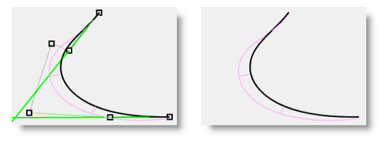
In this example found on page 99 of the level 2 training manual, first on each endpoint of a curve, a tangent line is drawn by using Line command with Extension option. Each of the 2 lines maintains the tangency direction of an original curve from each end point and coming back towards the curve.

Then use the Rebuild command (Edit menu: Rebuild) to rebuild the curve. In the Rebuild Curve dialog, change the Degree to 5 and the Point Count to 6 points. Uncheck Delete input, check Create new object on current layer. It is better practice that the original curves are kept in a separate layer. Click the Preview button. Note how much the curves deviate from the originals.Although there is a Rebuild option in many commands such as Loft, rebuilding the curves before lofting them gives you control over the degree of the curves as well as the number of control points.
Lock the Original Curves (in a separate layer if you can). We need to see these curves but we do not want to be able to select them. Select one of the rebuilt curves, and turn on the Control points and Curvature graph.
 Fair the curve by adjusting points until it matches the original curve closely enough. Start by moving the second control point from each end of the rebuilt curve onto the tangent line. Use the Near object snap to drag along the tangent line.
Check the curvature graph to make sure the curve has smooth transitions. The curves are fair when the points are adjusted so the rebuilt curves match the original locked curves closely, with good graphs.
In this example found on page 99 of the level 2 training manual, first on each endpoint of a curve, a tangent line is drawn by using Line command with Extension option. Each of the 2 lines maintains the tangency direction of an original curve from each end point and coming back towards the curve.

Then use the Rebuild command (Edit menu: Rebuild) to rebuild the curve. In the Rebuild Curve dialog, change the Degree to 5 and the Point Count to 6 points. Uncheck Delete input, check Create new object on current layer. It is better practice that the original curves are kept in a separate layer. Click the Preview button. Note how much the curves deviate from the originals.Although there is a Rebuild option in many commands such as Loft, rebuilding the curves before lofting them gives you control over the degree of the curves as well as the number of control points.
Lock the Original Curves (in a separate layer if you can). We need to see these curves but we do not want to be able to select them. Select one of the rebuilt curves, and turn on the Control points and Curvature graph.
Friday, September 18, 2015
Curve fairing to control surface quality
Going through Rhino 5 Level 2 training manual, I often learn details in 3D modeling of which I was not aware.....
There is an exercise titled "Curve fairing to control surface quality" in the manual,
it teaches me that many curves in Rhino coming from many sources need to be optimized for quality. It mentions curve fairing as a technique used in Rhino to optimize a curve for 3D modeling. It defines fairing as "a technique used to simplify curves while improving their curvature graphs and keeping their shape
within tolerance." It also states: "it is especially important to fair curves that are generated from digitized data, intersections, extracted isocurves, or curves from two views."
It explains that single-span curves work better for this fairing process. What is a single span curve? A single span curve is a curve that has one more control point than the degree. For examples a degree 3 curve with 4 control points, and so on.
To fair a curve, it starts with rebuilding a curve. This is when Rebuild command is used. In the dialog window of Rebuild, the number of control points and the degree of curve can be updated. As a single-span curve works best in curve fairing, so it is seen in the following image that in the Rebuild Curve dialog, change the Degree to 5 and the Point Count to 6 points. Uncheck Delete input, check Create new object on current layer.


I can then analyze the surface with CurvatureAnalysis. It will shows the smooth transitions in the false color display, indicating smooth curvature transitions in the surface.
There is an exercise titled "Curve fairing to control surface quality" in the manual,
it teaches me that many curves in Rhino coming from many sources need to be optimized for quality. It mentions curve fairing as a technique used in Rhino to optimize a curve for 3D modeling. It defines fairing as "a technique used to simplify curves while improving their curvature graphs and keeping their shape
within tolerance." It also states: "it is especially important to fair curves that are generated from digitized data, intersections, extracted isocurves, or curves from two views."
It explains that single-span curves work better for this fairing process. What is a single span curve? A single span curve is a curve that has one more control point than the degree. For examples a degree 3 curve with 4 control points, and so on.
To fair a curve, it starts with rebuilding a curve. This is when Rebuild command is used. In the dialog window of Rebuild, the number of control points and the degree of curve can be updated. As a single-span curve works best in curve fairing, so it is seen in the following image that in the Rebuild Curve dialog, change the Degree to 5 and the Point Count to 6 points. Uncheck Delete input, check Create new object on current layer.
This makes the curves into single-span curves. Single-span curves are Bézier curves. A single-span curve is a curve that has degree +1 control points. While this is not necessary to get high quality surfaces, it produces predictable results. I can also combine Divide command with PointDeviation to detect the deviation of the points on a curve and to adjust the points' positions until the points are located within the range of good deviation and are identified in blue as "good points".

The end result of a new surface from these curves after fairing will be that the shape and quality of the surface has very few isocurves but it is very close to the shape of the first surface.
I can then analyze the surface with CurvatureAnalysis. It will shows the smooth transitions in the false color display, indicating smooth curvature transitions in the surface.
Wednesday, July 8, 2015
Rhino 3D: Rebuild a curve
One thing that I like about Rhino is its ability to rebuild
a curve or surface. The function of Rebuild in Rhino is most useful for me in
straightening a curve or smoothing a surface. Here I would like to cite an
example I found in Rhino 5 User’s Guide.

To make a curve smooth, I can rebuild the curve to remove
excess control points. That means I have to select that curve and use the Rebuild command to
reduce the number of points and set the degree. The rule of thumb in creating
curves for modeling is: “Do not use more points than you absolutely need” as
instructed in the user guide.
I can turn on the CurvatureGraph command to check the curves at
the same time for smoothness. CurvatureGraph command can display the curvature
graph. If the curvature graph is still not satisfactory, then I will move the
control points until I have a smooth graph.
As shown in the below image, the yellow curve is a revised
one from the green one. The point count is 12 and the degree of cure is 5. Looking
at the white curvature graph, I can see the curvature graph on left end of the
yellow curve is merge with yellow curve. It indicates that there is tangent or
smooth transition from the yellow curve to its adjacent flat line.

Friday, June 5, 2015
Rhino 3D: Anything you can do I can do better!
As generally believed, there are some fine details that set
Rhino apart from parametric CAD. In one aspect, Rhino can create a surface that
exists mathematically, while the surface is hard to be made by an apparent set
of rules in parametric modeling. Parametric CAD programs have more stringent
conditions on creating a surface. If the conditions are satisfied, then the
surface can be generated. If not, the surface will fail. One of the reasons for
that I figure is because parametric CAD is designed for engineering and in some
cases scientific applications. The 3D models or surfaces in parametric CAD must
be precise and anchored on measureable parametric data. However in Rhino, it
provides you with multiple ways to create a surface that is hard to defined in
mathematical terms even though the surface exists mathematically.
Look at this example of Lofted surfaces from Rhino 5 Level 1 training manual, Exercise 59— Canoe. (The manual is here)When you prepare sketch profiles (curves) to make a lofted surface in Solidworks, the program will have to make sure the newly lofted surface go through every sketch profile (curves) with smooth curvilinear transition. It is rigidly constructed and conformed to the sketch profiles. Whereas in Rhino, you can have some other options:

Above are the finished Canoe and its original sketch profiles (curves)

In the Loft Options dialog box, the default of Style is Normal. A surface is fitted over the curves just it can be done in Solidworks.

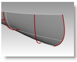
Look at this example of Lofted surfaces from Rhino 5 Level 1 training manual, Exercise 59— Canoe. (The manual is here)When you prepare sketch profiles (curves) to make a lofted surface in Solidworks, the program will have to make sure the newly lofted surface go through every sketch profile (curves) with smooth curvilinear transition. It is rigidly constructed and conformed to the sketch profiles. Whereas in Rhino, you can have some other options:

In the Loft Options dialog box, the default of Style is Normal. A surface is fitted over the curves just it can be done in Solidworks.
Or, in the Loft Options dialog box, you can switch Style to
Straight sections, A surface is fitted through the curves, but the sections are
straight between the curves. It is much like a poly model.
Or, in the Loft Options dialog box, switch Style to Loose, a
surface is created that uses the same control points as the curves. The surface
follows the curves more loosely. Use this option when you want the surface to
conform to the control points of the input curves.
This is an example that illustrates one of the
advantages a CAD user can see in Rhino over CAD programs like Solidworks – its
versatility and flexibility in getting surface made.
Subscribe to:
Posts (Atom)