Thursday, July 23, 2015

Favorite humanistic fonts for product and information graphics


Helvetica is almost the default typeface that spears in many products of information design, such as control panels on products and directional sign in public place. Its popularity was documented by Gary Hustwit’s 2007 film “Helvetica”. However, while Helvetica can be said as the most widely adopted san serif typeface, there is a trend for over 20 years toward applying more humanistic sans serif typefaces in information graphics.

The main reason why they are called humanistic typefaces I think is because their creators intend to infuse the calligraphic details in typeface design. In doing so, with some variation in line width, the typefaces become more legible than other sans serif fonts. When being called humanistic, they also appeal to people’s cultural side and associate themselves with fonts from various historic periods. This is a sharp contrast against typical san serif fonts such as Helvetica, which seems very strict, rigid and mechanical.

Among those humanistic sans-serif fonts, FF Meta is a notable font designed by the influential German typeface designer Eric Spiekermann. He also co-authored a book, Stop Stealing the Sheep, in 1993, an interesting read that introduces readers to find the right fonts that properly express ideas, emotions and so on. Because you need to pay font sellers such as Myfont.com to get FF Meta, I have found Colaborate font as an alternative for free online and use it often in my designs that involves with informational display. I discovered that Colaborate is equally good and very elegant as well. So you may consider using Colaborate Thin to create that eloquent effect next time when you think of being chic and neat. So far I have used the free version of Colaborate and have not experienced with any virus, and you may download the free fonts Colaborate here but use your own discretion. 
Incidentally I learned lately that as Cooper Hewitt Smithsonian Design Museum reopened its door to public this year, it has commissioned a new custom-designed typeface by Chester Jenkins. It used the new font to rebrand itself in logo, prints and webs. And it is also free to download. I just downloaded and installed it on my computer. The font package includes all types of line width from heavy, bold, book, light, to thin and in many ways the variations of the font are very similar to Colaborate. Therefore I will try my hand on it next time for upcoming information design or presentation.


Wednesday, July 8, 2015

Rhino 3D: Rebuild a curve

One thing that I like about Rhino is its ability to rebuild a curve or surface. The function of Rebuild in Rhino is most useful for me in straightening a curve or smoothing a surface. Here I would like to cite an example I found in Rhino 5 User’s Guide.

To make a curve smooth, I can rebuild the curve to remove excess control points. That means I have to select that curve and use the Rebuild command to reduce the number of points and set the degree. The rule of thumb in creating curves for modeling is: “Do not use more points than you absolutely need” as instructed in the user guide.
I can turn on the CurvatureGraph command to check the curves at the same time for smoothness. CurvatureGraph command can display the curvature graph. If the curvature graph is still not satisfactory, then I will move the control points until I have a smooth graph.
As shown in the below image, the yellow curve is a revised one from the green one. The point count is 12 and the degree of cure is 5. Looking at the white curvature graph, I can see the curvature graph on left end of the yellow curve is merge with yellow curve. It indicates that there is tangent or smooth transition from the yellow curve to its adjacent flat line.
 

Monday, July 6, 2015

Relevant details for consumer electronic product design


One day in June when my wife and I strolled down the street in Quebec City during our vacation, a company’s sign caught her attention. It says Advanta Design Industriel. She guessed it must be an industrial design firm. We peeped through the window and, yes, it is a design studio with people working in there. She wanted me to take a picture of the sign for our vacation memory, but I thought why bother, I have seen so many design firms in the U.S.

After the trip, I decided to google the company and found its website. Wow, Bang! This company does put out some good stuff on its site that is worth noting. Mainly you will find it make itself very resourceful regarding the mechatronic design if you go to its expertise page. Right there you will get a glimpse of what an industrial designer needs to know about the details as well as inner working for the electronic products they may design. For example, a designer can learn:

1)      How the clear or translucent lightpipe can work as a conduit for transmitting LED light from PCB board to exterior control/display panel. I consider lightpipe design is crucial to dictate the locations of LED lights on control/display panel as in many projects I have to deal with this issue. It is related to PCB layout and physical sizes and locations of LEDs.

2)      How thin walls can be designed and molded. Thin wall plastic enclosure sometimes are created inevitably even engineers will suggest a designer not to. Here Advanta gives you the idea on how to make the thin wall design works – by using high pressure injection molding to increase the mold flow speed or by choosing the right resin to facilitate the mold flow.

3)      Soft touch overmolding – as the demand for good gripping on the handheld products escalates, the textured and soft touch are becoming the de facto finishing of product exterior surfaces. You will see TPE (thermoplastic elastomer) type of materials like Kraton or Santoprene are widely used in creating these soft touch gripping surfaces.

4)      Overmolding that in some cases combines soft and hard materials into one single part. Overmolding is prevalent in many product details where reducing the abrasion between components in an assembly or creating inmold decoration is required.

These design details featured in Advanta’s expertise page will be relevant to many industrial designers and will certainly help inspire them to unleash their creativities for more design options that take roots in gracious details. 

Friday, June 5, 2015

Rhino 3D: Anything you can do I can do better!

As generally believed, there are some fine details that set Rhino apart from parametric CAD. In one aspect, Rhino can create a surface that exists mathematically, while the surface is hard to be made by an apparent set of rules in parametric modeling. Parametric CAD programs have more stringent conditions on creating a surface. If the conditions are satisfied, then the surface can be generated. If not, the surface will fail. One of the reasons for that I figure is because parametric CAD is designed for engineering and in some cases scientific applications. The 3D models or surfaces in parametric CAD must be precise and anchored on measureable parametric data. However in Rhino, it provides you with multiple ways to create a surface that is hard to defined in mathematical terms even though the surface exists mathematically.
 
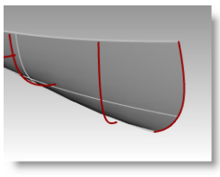
Look at this example of Lofted surfaces from Rhino 5 Level 1 training manual, Exercise 59— Canoe. (The manual is here)When you prepare sketch profiles (curves) to make a lofted surface in Solidworks, the program will have to make sure the newly lofted surface go through every sketch profile (curves) with smooth curvilinear transition. It is rigidly constructed and conformed to the sketch profiles. Whereas in Rhino, you can have some other options:

 
Above are the finished Canoe and its original sketch profiles (curves)
 

In the Loft Options dialog box, the default of Style is Normal. A surface is fitted over the curves just it can be done in Solidworks.


Or, in the Loft Options dialog box, you can switch Style to Straight sections, A surface is fitted through the curves, but the sections are straight between the curves. It is much like a poly model.


Or, in the Loft Options dialog box, switch Style to Loose, a surface is created that uses the same control points as the curves. The surface follows the curves more loosely. Use this option when you want the surface to conform to the control points of the input curves.


This is an example that illustrates one of the advantages a CAD user can see in Rhino over CAD programs like Solidworks – its versatility and flexibility in getting surface made.

Wednesday, June 3, 2015

Quest for the strength of Rhino 3D

I have  came to know of Rhino 3D for more than 10 years. In the beginning, when it was still in its infancy, I downloaded the free trial version to play for a while. At the first sight of Rhino 3D, I was quite amazed because I thought how a NURBS modeling program can be so affordable. Back then I used Alias Studio at work to create some complex curvilinear shapes that were then hard to be modelled by Solidworks I used every day. Honestly I was a bit distasteful of Alias Studio. It was a program built on Silicon Graphics workstation and was very hard to use because it was so powerful and has so many variables that need my attention and tweaking. I was lost often in using Alias and thus quipped that learning to use Alias is like studying rocket science.

Then Rhino 3D came. It was offered as a low-cost but powerful enough NURBS modeling program under a unique business model of Robert McNeel & Associates. Though I downloaded the program to try but never paid a full attention to learn it. My company even sent me to learn it at Magnetic Visions in Brooklyn, NY in 2011. Through the training I learned the basic modeling skills in Rhino 3D, but thought that why bothering with Rhino while in Solidworks I can use hybrid of solid/surface modeling techniques to take care of most 3D modeling task.
I decided lately to dig deeper into learning Rhino and encountered several issues, which I have to get used to. The issues I have with Rhino 3D are: first of all, it is a program born out of AutoCAD era, meaning its interface bears the resemblance of CAD programs in that era. It has a command prompt window. Even though there is an alternative icon in pulldown menu to get to each command, a user still has to use command lines to get to the options under a command most of the time. Some commands are followed by the dialogue windows once selected, but only a few. Secondly, to make a sketch for modeling, the sketch normally falls on front, side, top or construction plane. This is something I have been struggling with because I am so used to parametric modeling in Solidworks where I can simply click on a plane surface to start a sketch. So far as I know, in Rhino to start a sketch it is easier to adhere the sketch to front, side, top or construction plane. Elevator Mode may be the only antidote I have found so far to break a 2D sketch away from the construction plane to which it adhere. Thirdly, Solidworks has simplified the steps of many model features that employ Boolean algorithm, for example, shelling a solid block. Shell command only becomes available since Rhino 5. Fourthly and the least is that Rhino is not a CAD program for engineers, it lacks the parametric modeling features and does not have a design feature tree that can be rolled back and forth as in Solidworks.

So that I have to bear in mind that certain modeling tasks can be done better elsewhere than in Rhino. I just have to find the strength of Rhino where other CAD programs fall short or cannot do better. Keep reading ....

Tuesday, June 2, 2015

Rhino 3D: 4-sided surfaces


In Rhino v5.0 training manual level 1, there is a useful exercise to compose a surface model from 6 4-sided surfaces. This manual can be found at Rhino 3D website at: https://www.rhino3d.com/download/rhino/5.0/Rhino5Level1Training

In Exercise 57 page 162 - Creating simple surfaces, 6 ways to make a 4-sided surface are demonstrated:
1. Planes:
From the Surface menu click Plane, and then click Corner to Corner.


2. To create a vertical plane:
From the Surface menu click Plane, and then click Vertical.


3. To create a plane from 3 points:
From the Surface menu click Plane, and then click 3 Points.
Beware that, in this method, SmartTrack is used to track a point from the top of the vertical plane for height of the place. When doing this, I need to turn on Object Snap (with End and Point checked) on status bar and drag the cursor to lightly touch the top corner of the vertical plane I just made in Step 2. Drag the tracking point until the surface is tilted slightly and click.

4. To create a plane from corner points:
From the Surface menu click Corner Points.

When picking the points in the next four steps, I must pick them in a clockwise direction. I tried this command and found that I can make not only 4- but 3-sided plane with this command.

5. To create a surface from planar curves:
Turn Planar mode on in status bar. Draw a curve that starts and ends at the top of the two vertical surfaces as shown below. Planar mode keeps this curve on the same plane as the surface corners.
From the Surface menu click Planar Curves.

6. To create a surface from edge curves:
From the Surface menu click Edge Curves.


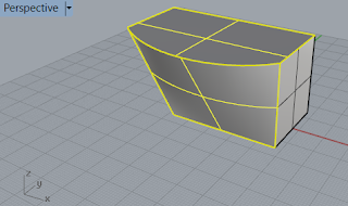
This is an excellent exercise that guides me through 5 more unique ways to make 4-sided surface except the simplest rectangle plane surface. But these surfaces are still independent from one another except ever 2 surfaces share one of the 12 edges in the model. I still can move a surface by click and drag it.

I will have to use Join command to stitch them together  like this:


Wednesday, May 27, 2015

T-Splines in Rhino: preparing NURBS surfaces in Rhino for T-Splines

When preparing T-Splines optimal surfaces in Rhino, I use Rebuild command to have enough control points on the surfaces. In this tutorial (https://youtu.be/JZ_bA_4XTpg), it teaches me how to prepare Rhino's NURBS surfaces to be used in T-Splines.

Plan surfaces in Rhino are all degree 3. It means the minimum point count in the U or V direction is 4. When the surface with 4 points in U or V direction is converted in T-Splines, I will get one single face. But if I increase the point count to 5 in U or V direction, I will get 2 in both directions or 4 faces total.

So it is easier for me to think in terms of how many faces are in my model when I convert them into T-Splines. If I want X faces in U or V direction in my T-Splines model, then I rebuild my NURBS surface to X plus 3 control points in that direction.